
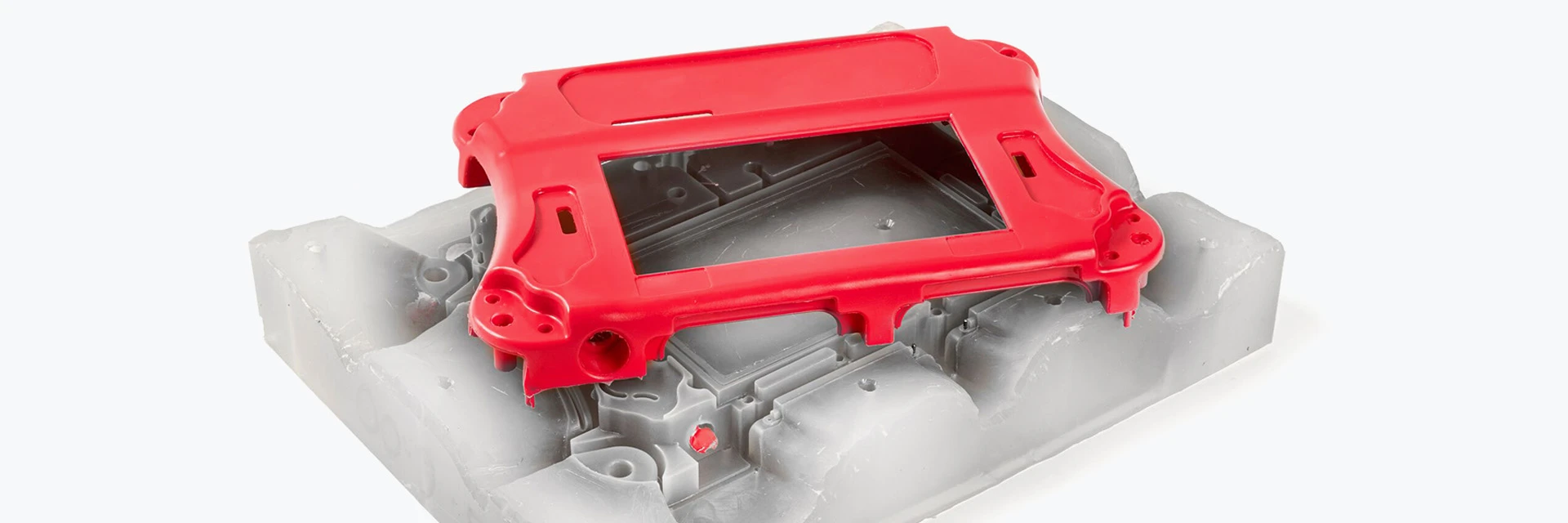
Common engineering formats include:
- 3D: STEP/STP, IGES/IGS, Parasolid and STL
- 2D: DWG, DXF and PDF with tolerances and datums
Provide a STEP file and dimensioned 2D drawing to help us review assembly relationships and tolerance stacks.
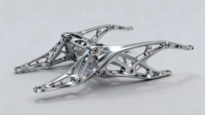
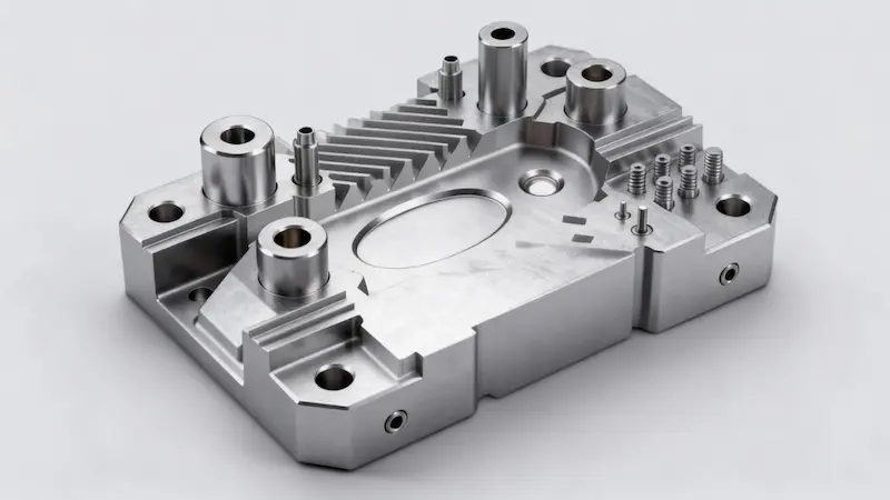
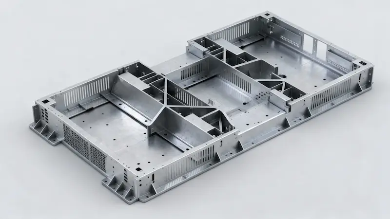
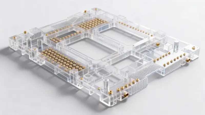
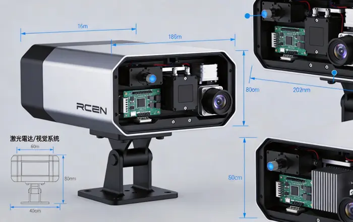
Component manufacturing for robots, joint modules, end effectors and automation systems, from prototype validation through pilot builds and production.
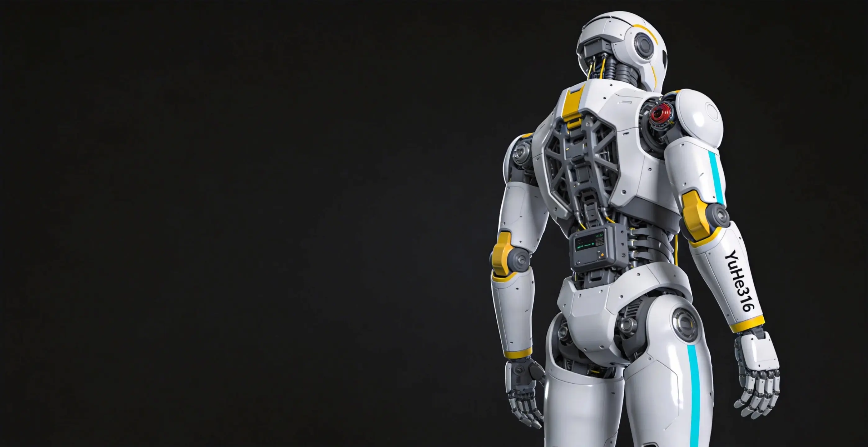
Robotics components require stability in motion as well as accurate dimensions.
Control weight while maintaining stiffness, with attention to distortion and vibration in thin walls and cantilevered structures.
Key considerations:
Components in a motion system need defined fits, alignment and operating clearances to allow reliable movement without unintended interference.
Key considerations:
Assembly performance depends on consistent datums and geometric tolerances as well as individual dimensions.
Key considerations:
Repeated motion and loading can lead to loosening, wear and loss of positioning accuracy. Define the required service conditions and inspection points when planning the parts and assembly.
Key considerations:
We manufacture custom joint, frame, sensor, control hardware and end-effector components for complete robots and subsystems. Process selection considers precision, stiffness, fit and operating requirements, with support from prototypes to repeat production.
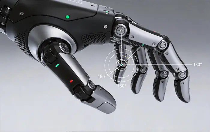
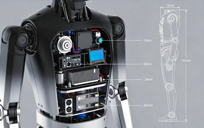
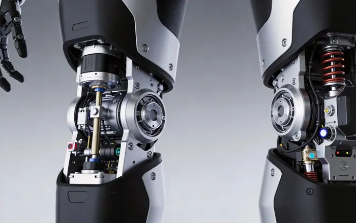
Choose processes for prototype validation, pilot builds and production based on part geometry, material, quantity and project requirements.
Robotics components must assemble correctly, move reliably and remain consistent across batches. We address fit, tolerance accumulation, weight, design changes and production readiness through engineering review and manufacturing planning.
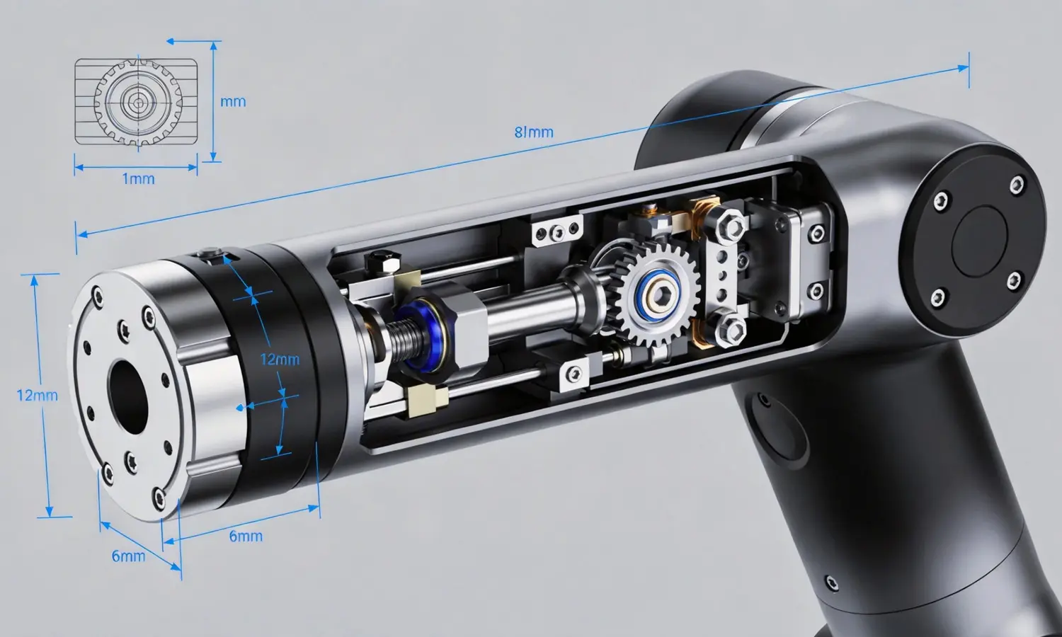
Review hole patterns, datums and clearances to reduce binding, noise and uneven wear. Define process controls for the fit between connectors and joint modules.
Review coaxiality, parallelism, position and the relevant datums across the assembly. Identify the dimensions that contribute most to accumulated error and define appropriate inspection and fit checks.
Review thin walls, pockets, ribs and connections within weight limits. Match materials and processes to reduce distortion, vibration and fatigue risks.
Use design reviews and process planning to identify difficult features, unnecessary operations and potential rework. Select 3D printing, CNC machining, sheet metal fabrication or injection molding according to geometry, quantity and development stage.
Control drawing revisions, inspection criteria and critical process parameters from the prototype stage to support consistency and traceability as quantities increase.
Common engineering formats include:
Provide a STEP file and dimensioned 2D drawing to help us review assembly relationships and tolerance stacks.
Processes can be combined to meet stage-specific performance and quantity requirements.
Trial assembly and inspection data can be provided as agreed.
Yes. We support prototype validation, pilot builds and production with a manufacturing plan suited to each stage.
Lead time depends on geometry, process, materials, quantity and inspection requirements.
Contact our team to arrange an NDA before sharing sensitive drawings or project information.